GPIO (General Purpose Input Output) Pins - Raspberry Pi tutorial
Hello and welcome to part 6 of the Raspberry Pi tutorial series. In this tutorial, we're going to be introducing and using the GPIO (General Purpose Input Output) pins on our boards.
These pins are directly connected to our Broadcom chip, so this is a "proceed at your own risk" tutorial. You can fry your Pi with a simple mistake plugging into the wrong pin. That said, most of the awesome functionality of the Raspberry Pi comes from these pins, so it's a rewarding thing to learn.
The first thing you'll want to do is familiarize yourself with which of the pins you can use, and what they do. The best diagram in my opinion is from Adafruit:
Broadcom (BCM) pin names:
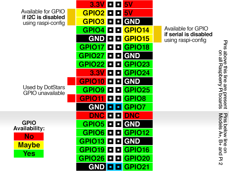
To compare these to your Raspberry Pi, orient the pins so that they are at the top right of the board.
All those green pins are your typical GPIO pins. The yellow ones can be used if you need them by disabling some features in raspi-config. The order of pins never changes, no matter which version of the Raspberry Pi model B you have, starting from the top down. The later models more pins over time, which is depicted here.
The GPIO pins are the main ones of interest to us, and these pins have basically two states: high or low, and we can combine these binary choices to create many more outcomes with circuits to interact with the physical world with our programs.
For now, let's just use the high and low signals to turn on an LED light on based on our programming.
What you'll need for this (besides your Raspberry Pi):
- 10 x Male-to-Female jumper wires.
- 1 x Breadboard
- 3 x LED light
- ~6 x Resistors (between 300 and 1K Ohm). You will need at least 1K and 2K ohms for the distance sensor, then ~300-1K resistance per LED bulb. You probably should just buy a kit, they're super cheap.
- 1 x HC-SR04 Ultrasonic Distance Sensor
We'll be using a few more M-F jumper wires in the next tutorial, two more LEDs, and more resistors, so it's good to buy a kit.
The only variable here is the LED light. LED lights are going to want to draw different amounts of power depending on the light, which can burn out your Raspberry Pi. One decent choice is to have a variety of resistors, start with a large resistence and gradually decrease it until you're happy with the LED light's intensity. Most LEDs will work just fine with 300-1K Ohm resistance. The more resistance you use, the dimmer the LED will be. If you use enough resistance, you won't even see the LED. If you get to 300 Ohm resistance and you still cannot see the LED at all, then, chances are, that bulb is bad, try another, or it could also be your circuit is incorrectly connected, the jumper wire is bad...etc, but it's usually the bulb. Also, do make sure you have the bulb plugged in right. If you have a longer lead, that suggests that's the positive end, so that should go next to the GPIO jumper, and the negative end should go with the resistor side.
First, if you're not familiar with a breadboard, the idea of one is to help you to quickly test a circuit, as well as to help you learn about working with circuits without doing any soldering.
A typical breadboard looks something like:
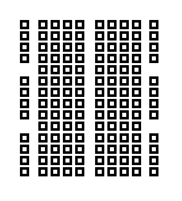
The rows along the edges are connected vertically, and the center portions are connected horizontally. Any time there's a larger gap, like down the middle of this board, that's not connected. If you want these portions to be connected, you have to connect them.
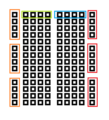
Each of the boxes illustrates which parts to connected.
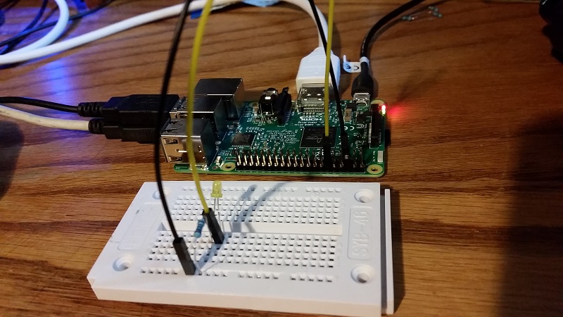
Before you proceed, turn off your Raspberry Pi ($ sudo shutdown -h now), and unplug it.
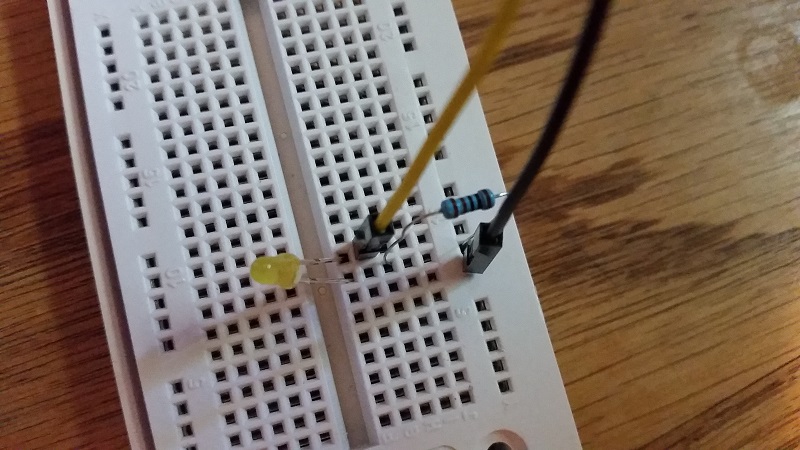
For our circuit, we want:
The filled in boxes are the jumper wires by color, and the boxes themselves are the pins on the pi or the openings on the breadboard.
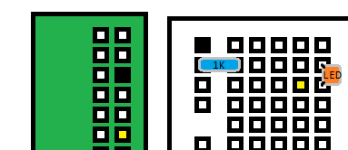
A physical picture:
On the Raspberry Pi's pins:

Now you can turn your Raspberry Pi on, and we'll begin the code.
All together:
In your Pi's terminal, do:
$ sudo apt-get install python-rpi.gpio
You probably already have it, but just to make sure. Next, create a new python file, and let's begin:
import RPi.GPIO as GPIO
import time

GPIO.setmode(GPIO.BCM)
The reason we want to set the mode here is because there are actually two labels for all of the pins, Broadcom (BCM) and board (BOARD). The board option will let you refer to the pin's actual number on the board, and the Broadcom number is the actual pin number that the Broadcom chip considers it to be. It seems to be that BCM specification is the *actual* pin number, so we'll use that. I like this anyway, since it always forces me to check the diagram and be careful with my connections.
Continuing our script:
GPIO.setup(18, GPIO.OUT)
Here, we're setting up the pin to be a pin that outputs information. We can also set the pin to take in information instead. That is something we'll do in the next tutorial.
GPIO.output(18, GPIO.HIGH)
time.sleep(3)
Here, we tell pin 18 to output a high signal, and we'll pause for 3 seconds.
GPIO.output(18, GPIO.LOW)
GPIO.cleanup()
Finally, we change the pin's output to a LOW signal, and then we use GPIO.cleanup() to reset the pin's statuses to their default states before we're done with the program. We do this so that the next program that runs comes into a state that it expects. It's easy to forget and leave various pins on setup differently and find they act strange.
The full script:
import RPi.GPIO as GPIO
import time

GPIO.setmode(GPIO.BCM)

GPIO.setup(18, GPIO.OUT)
GPIO.output(18, GPIO.HIGH)

time.sleep(3)

GPIO.output(18, GPIO.LOW)
GPIO.cleanup()
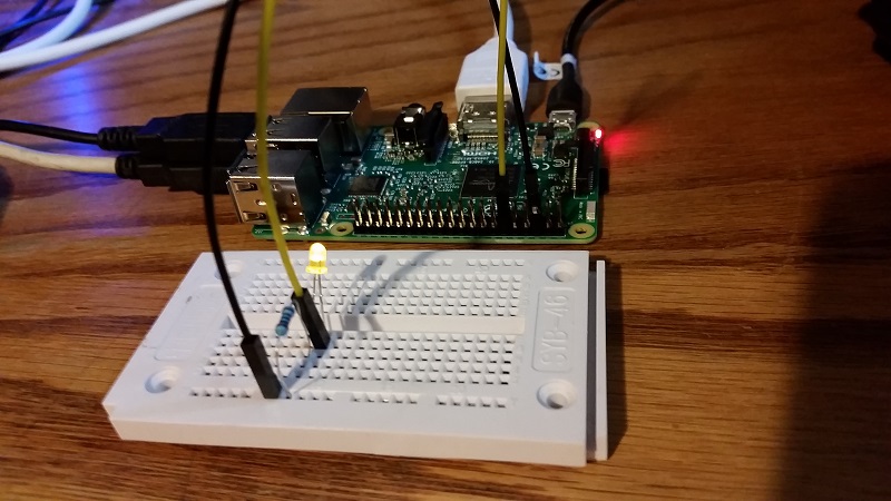
The result should be that the LED turns on for three seconds:
-
Introduction - Raspberry Pi tutorial
-
Remote Access with Raspberry Pi tutorial
-
Terminal Navigation - Raspberry Pi tutorial
-
Raspberry Pi Camera Module - Raspberry Pi tutorial
-
GPIO (General Purpose Input Output) Pins - Raspberry Pi tutorial
-
Input from a Sensor via GPIO - Raspberry Pi tutorial
-
Garage Stoplight GPIO Project - Raspberry Pi tutorial